KO
|
EN
gitlite — search
Search
#python
#java
#python3
#arduino
#golang
#machine-learning
#rust
#html
#flask
#javascript
#seismology
#nodejs
cudabrot
★ 13
Open GitHub ↗
A CUDA renderer for the Buddhabrot fractal
Download README (.md)
Explore Similar Repositories
multitenancy
:
No description available.
svgize
:
A command line tool to make transparent JPEG images with SVG.
DroidStreamingDemo
:
Audio streaming demo in Android app
ResNet
:
Tensorflow ResNet implementation on cifar10
RPi_AutoWifi
:
树莓派一键配网
// repository documentation
Was this content helpful?
★ 0
(0 ratings)
Select Rating:
★
★
★
★
★
Submit Feedback
Recent Feedback
×
Download README
Do you want to download the
README.md
file for
cudabrot
?
Download (.md)
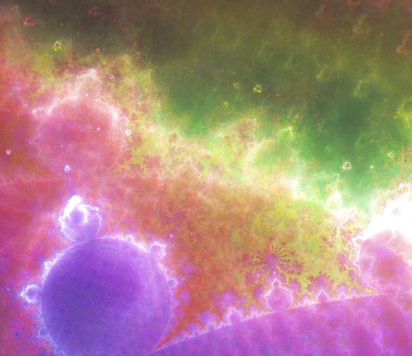
CUDAbrot: A "Buddhabrot" Renderer using CUDA or HIP =================================================== About ----- This project contains a small CUDA program for rendering the Buddhabrot fractal using a CUDA-capable GPU. I'm aware that there are at least two other github projects named "cudabrot", but both of them render the Mandelbrot set rather than the Buddhabrot. The Buddhabrot set is a variant of the Mandelbrot set similar to an [attractor](https://en.wikipedia.org/wiki/Attractor), and is generally more processor-intensive to render. Therefore, rendering high-resolution Buddhabrot images is an excellent application of GPU computing. For more information on how the Buddhabrot set is rendered, see the [Wikipedia article](https://en.wikipedia.org/wiki/Buddhabrot) for information about the algorithm and the relationship to the Mandelbrot set. Usage ----- To compile and run this program, you need to be using a Linux system with CUDA installed (the more recent the version, the better), and a CUDA-capable GPU. See below for instructions on AMD, using HIP. Compile the program simply by running `make`. Run it by running `./cudabrot`. A summary of command-line arguments can be obtained by running `./cudabrot --help`. Running the program will produce a single grayscale image. Typically, a colored Buddhabrot image is created by rendering several single- channel images with different parameters, then combining the results by assigning each single-channel image to a color in the output image. Compilation on AMD, using ROCm ------------------------------ This program has also been built and tested using ROCm 3.7 (but older versions probably work) on AMD GPUs. To use this, you'll need to have [installed ROCm](https://github.com/RadeonOpenCompute/ROCm), including `hip`, `rocRAND`, and `hipRAND` (these should be installed by default if you just follow the main ROCm installation instructions). Additionally, you'll need to ensure that `hipcc` and `hipify-perl` are on your `PATH`. The makefile also expects to be able to find `rocRAND` and `hipRAND` under `/opt/rocm/rocrand` and `/opt/rocm/hiprand`, respectively. If you satisfy all of the above requirements, then you should be able to compile the program by running `make hip`. This will produce a `cudabrot` binary that behaves the same way as the CUDA version. (Don't be intimidated by these instructions--check the makefile, it's actually very simple!) Examples and detailed description of options -------------------------------------------- All examples below were rendered using an NVIDIA GTX 970 with 4GB of GPU RAM. - `-d <device number>`: Example: `./cudabrot -d 0`. If you have more than one GPU, providing the `-d` flag along with a device number allows you to run computations on a GPU of your choosing. If the `-d` flag isn't specified, the program defaults to using GPU 0. - `-o <output file name>`: Example: `./cudabrot -o image.pgm`. This program is capable only of saving `.pgm`-format images, which are a simple grayscale bitmap format. Output images always use 16-bit grayscale. If left unspecified, the program will save the image to a file named `output.pgm` by default. - `-w <image width>`: Example: `./cudabrot -w 500 -h 500`. This flag controls the horizontal resolution of the output image, in pixels. Note that neither this nor `-h` (for controlling vertical resolution) affects resolution at which the complex plane is actually sampled. Image resolution doesn't directly affect computation speed, but it *will* have an impact on GPU and CPU memory required. For example, rendering a 20000x20000 image (`-w 20000 -h 20000`) takes at least 3 GB of GPU memory, so higher resolutions may only be possible on more-capable GPUs. - `-h <image height>`: Example: `./cudabrot -w 500 -h 500`. This is like `-w`, except it controls vertical resolution rather than horizontal resolution. - `-s <save/load file>`: If provided, this must be the name of a file into which the rendering buffer will be saved, for future continuation. If the file already exists when the program starts, it will be loaded (and then updated again before the program exits). This can be helpful if you need to "pause" long-running renders and resume them later. If already present, the file's size must match the expected internal size of the image buffer, but otherwise the file has no specified format. - `--min-real <minimum real value>`: Example: `./cudabrot -w 200 -h 100 --min-real 0.0 --max-real 1.0 --min-imag 0.0 --max-imag 0.5`. This, along with `--max-real`, `--min-imag`, and `--max-imag` control the borders of the output-image "canvas" on the complex plane. The rectangle specified must be well-formed (e.g. `--min-real` must be less than `--max-real`, etc.). If you want to set the canvas to something that isn't a square, then you'll also need manually adjust the output width and height to match the aspect ratio. For example, the above "example" command produces this image: . Note that "zooming in" will *not* necessarily speed up rendering, since points must still be sampled from across the entire Mandelbrot-set domain (from -2.0 to 2.0, and -2.0i to 2.0i). However, these settings can still be used for saving memory if you want to zoom in on finer details without rendering an ultra-high-resolution image. `--min-real` defaults to -2.0. - `--max-real <maximum real value>`. See the note about `--min-real`. `--max-real` defaults to 2.0. - `--min-imag <minimum imaginary value>`. See the note about `--min-real`. `--min-imag` defaults to -2.0. - `--max-imag <maximum imaginary value>`. See the note about `--min-real`. `--max-imag` defaults to 2.0. - `-t <time to run (in seconds)>`: Example: `./cudabrot -t 60`. This option specifies the amount of time, in seconds, to run the rendering on the GPU. The longer the time, the sharper the image will appear (especially at high resolutions or number of iterations). Passing a special value of -1 to `-t` will cause the program to run until it is interrupted by the user (using `kill` or CTRL+C on Linux, for example). Example: `./cudabrot -t -1`. If the program is run with `-t -1` and killed by the user, it will save the currently-rendered output image. This is the recommended way to run the program, if, for example, you want to render an image overnight. This option defaults to 10 seconds. - `-g <gamma correction>`: Example: `./cudabrot -g 2.0`. This option specifies the amount of gamma correction to be applied post-rendering. Gamma correction brightens darker areas of the image, which enhances the visibility of some details. In most cases, it may be easier to apply gamma correction post-rendering using a separate image editor (where changes can be previewed), but this option is available for convenience and scripting. This option defaults to 1.0 (no gamma correction). Example images: | `./cudabrot -w 200 -h 200 -m 10000 -c 8000 -t 30 -g 1.0` | `./cudabrot -w 200 -h 200 -m 10000 -c 8000 -t 30 -g 1.5` | `./cudabrot -w 200 -h 200 -m 10000 -c 8000 -t 30 -g 2.2` | | :---: | :---: | :---: | | 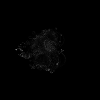 | 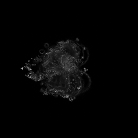 | 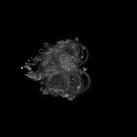 | - `-m <max escape iterations>`: Example: `./cudabrot -m 10000`. This option specifies the maximum iterations to follow each particle before determining whether it remains in the Mandelbrot set (meaning that its path is included in the Buddhabrot set). In short, increasing this value will include more fine details in the resulting image. This value defaults to 100, which is a fairly low value. See these examples: | `./cudabrot -w 200 -h 200 -t 10 -c 20 -m 100` | `./cudabrot -w 200 -h 200 -t 10 -c 20 -m 1000` | `./cudabrot -w 200 -h 200 -t 10 -c 20 -m 20000` | | :---: | :---: | :---: | | 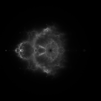 | 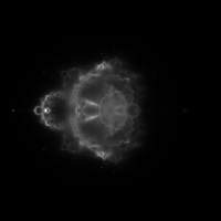 | 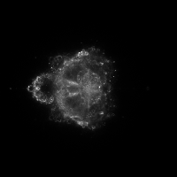 | - `-c <min escape iterations>`: Example: `./cudabrot -m 5000 -c 4000`. This option specifies the minimum cutoff for the number of iterations for which points must *remain* in the Mandelbrot set if they are to be included in the Buddhabrot. Increasing the minimum cutoff iterations will therefore reduce the "cloudiness" of the generated image, enhancing the visibility of the details produced using higher `-m` values. This value defaults to 20, which will produce a cloudy, nebulous image. See these examples: | `./cudabrot -w 200 -h 200 -t 30 -g 1.8 -m 20000 -c 20` | `./cudabrot -w 200 -h 200 -t 30 -g 1.8 -m 20000 -c 2000` | `./cudabrot -w 200 -h 200 -t 30 -g 1.8 -m 20000 -c 10000` | | :---: | :---: | :---: | | 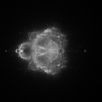 | 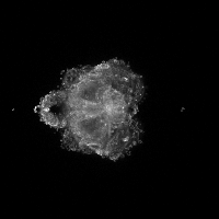 | 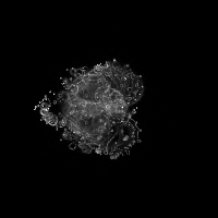 | Coloring the Buddhabrot ----------------------- The Buddhabrot rendering maps most easily to grayscale images, so coloring is left to post-processing. The "traditional" way to color a Buddhabrot is to generate several grayscale images using different minimum and maximum iteration values (the `-m` and `-c` options in this program). The grayscale images can then be combined into a single output image, with each grayscale image contributing to a different color channel in the output. A free program that can be used to combine grayscale images into a single color image exists [in a separate repository](https://github.com/yalue/image_combiner). Here's an example of how to create a color image, using the `image_combiner` tool linked above: ```bash ./cudabrot -g 2.0 -w 1000 -h 1000 -m 100 -c 20 -t 20 -o low_iterations.pgm ./cudabrot -g 2.0 -w 1000 -h 1000 -m 2000 -c 600 -t 20 -o mid_iterations.pgm ./cudabrot -g 2.5 -w 1000 -h 1000 -m 10000 -c 9000 -t 40 -o high_iterations.pgm ./image_combiner \ low_iterations.pgm blue \ mid_iterations.pgm lime \ high_iterations.pgm red \ color_output.jpg ``` Alternatively, I've found that mapping grayscale images to H, S, and L components of an HSL-color image results in a wide range of colors. I've included a script, `generate_hires_color_image.sh`, that uses this program to generate a nice looking, high-resolution (20k x 15x pixels) result. See the comments in the script for notes about additional requirements and operation. The following image is a cropped portion of the full-resolution output: